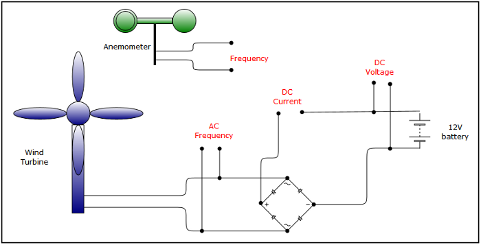
Arduino data logger (data acquisition system)The data logger, or data acquisition system, was made to try to get more information about the performance of the wind turbines I have been making. While the wind speed and output power could be read from meters it was nearly impossible to store the constantly changing data. The information I was hoping to collect would allow me to determine the efficiency of a wind turbine and compare different designs. The turbines were being used to directly charge a battery so the information I was interested in is:
The diagram illustrates the measurement points.  This was my first attempt at designing electronic circuits and started with a lot of research on the web. The Arduino open source processor board has been used by people doing similar projects and with its multiple ADC and digital inputs and a USB connection to a PC seemed a good starting point. A new Arduino Mega 2560 from ebay cost £25.00(UK) and proved to be quite easy to programme with good documentation. The Arduino board does not contain any permanent data storage, although it is possible to connect an SD card with suitable adapters, so I intended to use the board connected to a laptop and stream the data into a file on the laptop hard drive. The Arduino's ADC and digital ports are based on a 0 to 5V input range. The next problem was to take the measurement points in the diagram above and turn them into a signal suitable to be read by the Arduino. I don't claim any great experience of electronics so there may be better ways of doing this but the route taken seems to work. |