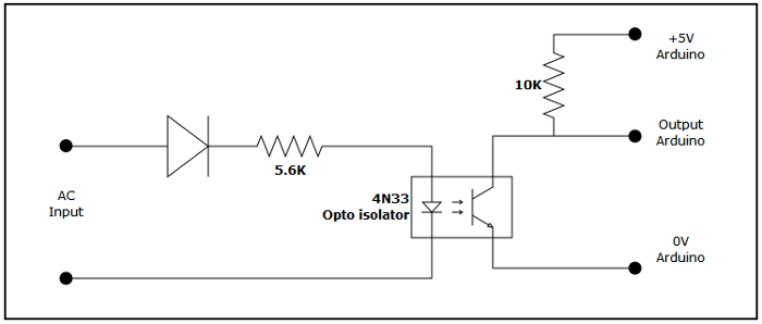
Arduino data logger - AC frequency measurementThe frequency is measured from the AC current from the wind turbine and used to calculate the rotational speed of the blades. Each pair of magnets in the alternator will produce one AC cycle, so an alternator with 12 magnets produces 6 cyles per revolution. (This assumes a direct drive between the alternator and rotor). The voltage will be held somewhere above 12V by the battery, but could rise much higher if the battery is disconnected so I was keen to isolate the Arduino from the power supply. I also wanted the frequency measurement would start at a low rotational speed, well before charging started. I used a digital input port on the Ardruino board, with an interrupt handler to detect changes in the state of the port. When the state changed the milli second time is stored and a count of the number of interrupts is incremented. At the end of the collection period (e.g. a second), the frequency can be calculated from (last time - first time)/number calls. The circuit used is a modification of the Opto isolator level shifting circuit on the Arduino web site. I'm only interested in changing the state of the digital pin so the diode means the input is half wave recified. The interrupt is triggered on rising (or falling) edge of the cycle when the output from the 4N33 opto isolator crosses 2.5V  CalibrationThe only calibration was to adjust the frequency for the number of magnets in the alternator. Each pair of magnets produce one cycle per revolution so turbine frequency = AC frequency * 2 / number magnets. I also checked the AC frequency against the multimeter I had previously been using. At times this circuit seems to generate more than one interrupt per cycle. It only seems to happen at certain speeds and when there is current flowing but they can be filtered out in the software. |