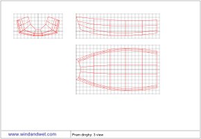
Free pram dinghy plan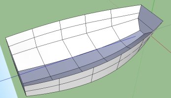
The boat was designed using some software I had written in the early 1990s (DOS running on a 386). This modelled the shape of the hull in 3D and evolved the shapes of the planks, allowing me to use a stitch and glue build method. The other great labour saver was the ability of the software to send the plan to an old wide carriage dot matrix printer loaded with continuous paper. The plans were then printed off in strips, taped together, laid over the plywood and a point used to mark the edges onto the wood. A 10cm grid printed on the plan allowed the parts to be aligned and assembled true. The end result was far more accurate than anything I could have achieved plotting the shapes by hand.
The drawings on this page were measured off the paper copies used to build the original boat.
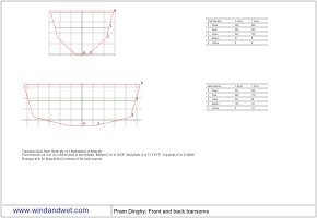
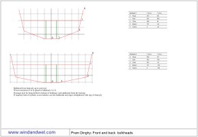
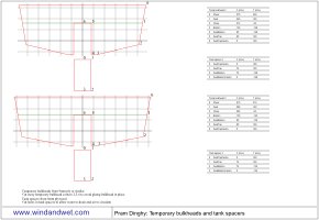
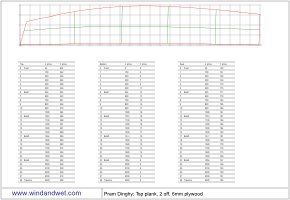
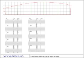
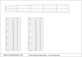
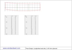
The same 10cm grid is used to generate the offsets, although not all of these are probably needed to create a smooth curve to the edge of the planks.
The top set of drawings can be printed on A4 paper and contain a scale view of the bulkheads and planks and the
offsets in millimetres used to plot the item full size.
Click on the image to bring up a full size drawing in a separate browser window which can be printed off.
At the bottom is a full size print out with all the components condensed onto a single 250cm by 56 cm drawing.
This can be printed out on 26 pages of A4 and then assemble using the grid as a reference.
If you have access to a larger format printer then so much the better.
The outline of each component has been drawn in a different colour to make it easier to distinguish
them in the jumble of lines. The form at the bottom allows you to select the paper size.
Full size dinghy plan (multiple pages)
Select your page size and click the "View plan" button.
A new window will open with the plan above drawn on separate pages that can then be printed.
This is slow to draw in Internet Explorer 8 or older.
To verify the measurements I'd taken from the original drawing I printed out the full size drawing (FireFox 3.5.7 browser and Epson 4050 A4 inkjet printer) with a page height of 280mm and width of 200mm. The result was 26 pages of A4 paper. If you do this please make sure the grid is the correct size as the results do vary between browsers.
In order to avoid compounding errors when the plan was stuck together I drew a 10cm grid on a piece of plywood and used this to align the paper. The grid was simple to draw using the machined edge of the plywood as a straight edge. A length of sheet metal clamped to some wood as a T square was used to draw the short lines of the grid. For the long lines the edge of another sheet of wood was used. Unfortunately, the only plank of plywood I had at the time was slightly narrower than the plan, but a wider sheet would make it much easier.
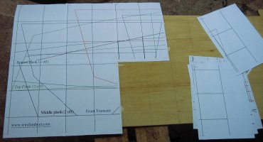
The pages of the plan were aligned with the grid and then tacked to the plywood with very small pieces of tape which would easily pull off later. The numbers in the top left corner give the X and Y coordinate of the page in the drawing. Where the pages overlapped I cut away the margin of the page so the red tick marks in the corners and the lines could be aligned, but the grid on the plywood was always used as the master. Working from one end the plan evolved quite quickly. When all the pages were tacked to the plywood I went over all the joins with some clear tape. It is best to avoid stretching the tape too much when you are sticking it to the paper otherwise it tends to pull the plan in when you move it. When all the joints were securely taped the plan was pulled off the plywood and the back taped up.
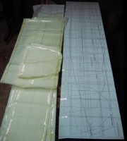
The plan was then laid out and the original drawings placed over the top to verify the shapes are the same. As I had no real use of a second identical dinghy I stopped at this point. It is important that if the plan is used to cut the full size sections that the grid lines are checked so they are straight and the overall length and width of the grid is correct to avoid distortion.
| ||||||||||
Links
| ||||||||||
I do not warrant the correctness of this content. The risk from using it lies entirely with the user. While using this site, you agree to have read and accepted the terms of use.
Copyright © 2026. All Rights Reserved. Privacy policy
