This is an explanation of the method used to create wind turbine blades from sections of pipe which have the optimum angle of attack along the length for a given tip speed ratio.
The equations has been taken from Hugh Piggott's blade design course which is the clearest description I have found of the theory.
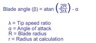
Calculate the blade angle
The angle of a wind turbine blade can be calculated using the equation below.
This assumes the the wind is being slowed to two thirds the free stream velocity at the rotor (Betz condition).

Calculate the blade chord
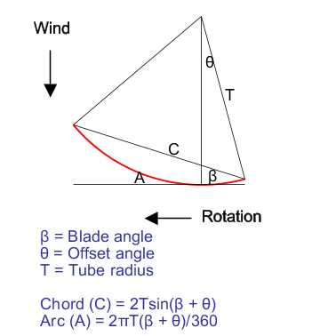
Having calculated the required angle of the blade it is possible to find the chord and arc around the pipe from the radius of the pipe. The trailing edge is assumed to be straight and parallel to the axis of the pipe but is offset by an angle allowing the designer to vary the width of the blade. In practice this also allows the blade to be bolted directly to the face of the hub. The leading edge is then calculated to give the required blade angle. The resulting blade will be wider at the root than the tip approximating to the optimum chord width.
The diagram shows the geometry of a cross section of the blade.

This assumes that the airflow is perpendicular to the blade. At the tip this will be a good approximation, but it will be less so close to the hub.
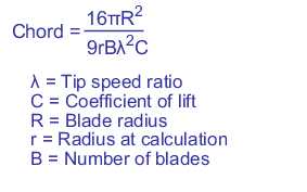
Theoretical blade chord
The calculations above allow you to generate a blade but do not give any idea of how wide the blade should be in order to extract maximum power i.e. what diameter pipe and offset should be used.
An equation for the approximate blade chord width can be found in the course notes
here .
The equation I use to get an approximate theoretical chord width is:

