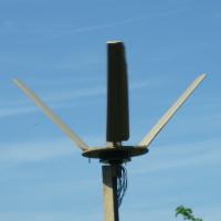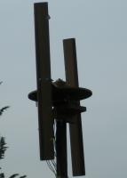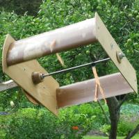
Experimental vertical axis wind turbines (VAWT)


These Darrieus style vertical axis wind turbines were my attempt to enlarge on the models I had made previously.
They gain their power from the lift generated by the blades unlike the Savonius wind turbines which use drag.
To make it easier to build and compare the designs I based them all on a common hub which was one I had made to test the axial flux alternators.
It is much the same as the hub used on the horizontal wind turbine except the disk was enlarged so it was easy to bolt on the rotors.
I initially started testing using the same axial flux alternator I had used on the horizontal wind turbines but the cut in speed charging a 12 V battery was too high for the vertical axis turbines.
To get over this I tried using a 6V battery as the load. This was partially successful, but in the end I made a new alternator stator.
This is single phase with 12 coils, each with 96 turns per coil, and 12 pairs of magnets on the rotor.
The coil was wound with a number of tap off points and wire sizes so the cut in and load could be adjusted, but in practise connecting all the coils in series meant charging started at around 190 rpm which seemed about right for these rotors.
When the alternator is charging there is a noticeable vibration which is transmitted down the pole supporting the turbine in a way I hadn't noticed on the horizontal turbines.
This suggests for any permanent installation it would be worth going for a 3 phase alternator which should be smoother running.
The voltage and current were measured to get some idea of the power being generated and the speed of the turbine can be found from the frequency of the AC voltage.
A 12 coil alternator will produce 6 cycle every revolution so the rpm could be found by multiplying the frequency by 10.
Wind speed measurement were made using a hand held anemometer.
The test were largely done in my garden which has a large number of surrounding trees and buildings.
The wind is generally very light and gusty and the direction variable which makes accurate wind speed measurements and efficiency calculation difficult.
It has been quite instructive to stick thin polythene (bin liner) tell-tales onto the blades, in a similar manner to the cardboard models.
This gives an indication of the relative speed of the blades and it is quite simple to see if the turbine was just being blow around by the drag on the downwind rotor or actually running.
The other good indicator was a tell-tale in the centre of the rotor between the blades so you can see the airflow through the rotor.
As the rotor starts this will blow out sideways, but when it is running unloaded, it will hang limp indicating very little air flowing through the turbine.
A gust or putting load on the turbine will cause it to blow out sideways.
These turbines are still very much experimental and in development and I hope to update the pages as I get more information.
|
I do not warrant the correctness of this content. The risk from using it lies entirely with the user. While using this site, you agree to have read and accepted the terms of use.
Copyright © 2026. All Rights Reserved. Privacy policy