Vertical axis wind turbine models
Vertical axis wind turbines always seem a good solution for use as small generators on boats as they have limited moving parts and also sweep a consistent area when running. There are small Savonius rotor models available but the frontal area, and hence power, are very small. To get a reasonable power a large bulky turbine would be required. A Darrieus type turbine seemed to be the obvious choice but I've never seen a small commercial turbine used on a boat and, unlike the horizontal axis machines, there were very few amateur examples I could find on the web.
Initially I attempted to get a small Darrieus turbine model working with thin fixed wooden blades, but this completely failed to run and showed no inclination to self start. I then went back to the drawing board and calculated the angle of attack of the blades through a complete rotation for various tip speed ratios. The equation for this calculation and discussions on VAWT aerodynamics can be found here

This shows that unless the tip speed ratio is reasonably high, a fixed blade would be operating at such a high angle of attack for most of the rotation that it will probably be stalled.
Just to see if I could get a Darrieus turbine to run and self start I made a series of models from wood and card. These are free running and generate no power. The bearing is a single ball race on the end of some studding with the rotor pushed onto the bearing. This has very low friction. There is very little startup torque and if any friction is present they won't start.
The "tassels" trailing from the rotors are very thin strips of light polythene (bin liner). These are an attempt to see the direction of the air flow. The ones on the blades appear to flow and the then lift when the blade stalls in a similar manner to "tell-tales" on a boat sail. The ones trailing from the back of the blades or arms indicate the relative speed of the blade to the airflow. If the "tell-tail" blows forward when the blade is in the downwind section of the path the tip speed is less than one. When it streams behind it is greater than one. When the "tell-tale" halfway down the arm streams behind the tip speed is greater than two. Faster than that, it's all a blur! I'm not sure how accurate this is but it gives an idea of the relative speed.
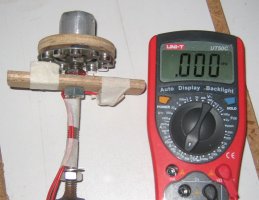
After the initial trials I attempted to measure the speed of rotation of the models and compare it to the wind speed. I made a small hub with a steel disk that pushed over the bearing. Twelve 10 * 5 mm magnets were arranged around the disk to make a small alternator rotor. A single stator coil wound with a large number turns of fine wire and held beneath the magnets. The output of the coil was fed into a multi meter set to read frequency. The 12 magnets will induce 6 full AC cycles every rotation so 1Hz on the multi meter is the equivalent of 10 RPM.

The hub worked well and a readings could be obtained at a couple of Hz. The rotation speed also matched the tachometer I used to test the alternator. The wind speed was measured using a hand held anemometer which was very sensitive to every change in speed and direction. Unless a site with a very smooth wind was used the wind speed would have large fluctuations but the inertia of the rotor would mean it would maintain a steady rotation speed. In general it seemed that the models would rotate with a tip speed around 2 to 3 times wind speed.
| ||||||||||||||
Links
| ||||||||||||||
I do not warrant the correctness of this content. The risk from using it lies entirely with the user. While using this site, you agree to have read and accepted the terms of use.
Copyright © 2026. All Rights Reserved. Privacy policy