Experimental vertical axis wind turbines (VAWT)V rotor vertical axis wind turbine (VAWT)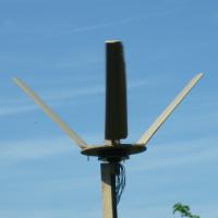
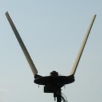

I made this because the small model V-rotor self started easily and ran smoothly.
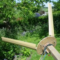
The rotor was designed to have 3 blades with the blades angled at 45° to the vertical.
The section is NACA 0018 curved to take account of the circular path and the chord width of the blades was a guess.
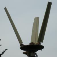
I've tried the rotor with the blades tilted up at a greater angle and also with both two and three blades.
The pictures show it in the various configurations.
With the blades angled more steeply the turbine would rotate faster when not under load but did not seem to have the torque to drive the alternator.
The 2 blade version suffered in a similar manner so it has largely been run as the original three blade design.
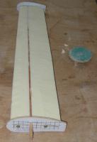
The blades are made of some scrap insulation foam stuck to a central spruce spar which takes the load.
To get the shape I cut root and tip templates that were about 10mm over size and then rolled the blade over a small sanding disk sticking up from a router table.
The end result was a reasonable shape but the spars always ended up standing slightly proud.
The foam was also very delicate and the thin trailing edge soon became a bit ragged.
When I covered the blades in parcel tape there was a noticeable improvement in performance.
The rotor starts easily and runs smoothly. It will produce power, but not as much as the best of the test bed designs.
If it is run with a tell-tale in the centre of the rotor it doesn't seem to be able 'block' the airflow when running unloaded, which suggest the chord width and sections are not optimal.
The damage to the blades, especially at the tips, does not help performance.
The design has a number of attributes (which could be seen as pros or cons)
| |||||||||||||||||||||||||||||||||||
I do not warrant the correctness of this content. The risk from using it lies entirely with the user. While using this site, you agree to have read and accepted the terms of use.
Copyright © 2026. All Rights Reserved. Privacy policy
