DIY wind turbine (2)

Hub
The axle is a length of 10mm mild steel rod with an M10 thread cut on each end. Pieces of 12mm tube are slid over the axle as spacers. When the turbine is assembled the nut on each end of the axle are tightened clamping the inner race of the bearings, stator and turbine body into one unit.
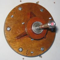
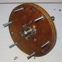
The hub is based around a length of 32mm aluminium tubing that was a push fit over the 30mm OD of the bearings. The back of the hub is two laminations of 9mm ply cut into a 160mm disk with a 32mm hole in the centre. This was cut out using a jig saw and then mounted on a drill and "turned" into a true circle. Since doing this I have cut larger plywood disks using a router mounted on a table and rotating the disk slowly against the cutter, which is a lot easier. The front of the hub a 9mm ply disk cut using a hole saw and the two are connected by 3 plywood webs.
The difficulty was to assemble the hub so it ran true. I first assembled the bearings on the axle and pushed the aluminium tubing over the bearings so it rotated freely. The large ply disk was then pushed over the aluminium and wedged with small scraps of wood until the face of the disk rotated without wobbling. I then fix it by running super glue in the joints. The plywood webs and front disk were then tacked together using more super glue checking it was all running concentric. When this was complete the centre of the hub and aluminium tube were covered in fibreglass cloth and resin and small fillets formed in the corners to provide a permanent bond.
The back bearing supports the thrust and the outer race of the front bearing floats in the aluminium tube. The back bearing is trapped in the aluminium tube at the front by a section of the split tubing pushed into the tube and retained with three self tapping screws. The back of the bearing is held by 3 screws with washers in the main plywood disk.
The hub is drilled for the bolts to hold the alternator on the back and the 3 PVC blades on the front.
| ||
Links
| ||
I do not warrant the correctness of this content. The risk from using it lies entirely with the user. While using this site, you agree to have read and accepted the terms of use.
Copyright © 2026. All Rights Reserved. Privacy policy