DIY wind turbine (1) Axial flux alternator
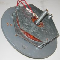
The axial flux alternator is 3 phase with 8 magnets and 6 coils. It is bolted to the back of the large plywood disk on the hub.
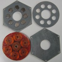
Two rotor plates were made from 3mm galvanised steel cut into a hexagon with a large hole in the centre. 5mm bolts through the corners of the hexagons held the plates to the back of the hub and the clearances could be adjusted using nuts. The 8 neodymium magnets (20 mm OD, 5mm thick) were simply placed on the steel plate with the centres on a 40mm radius and held in place with a thin plywood former. The polarity of the magnets alternated around the rotor and the magnets on opposite plates attract. I didn't want to glue the magnets to the plate so I could play with the design if required.

The stator was made of 6 coils each with 120 turns of 24 SWG (0.56mm) wire. These were wound around 6mm plywood cores and pretty much filled the available space when centred on the 40mm radius. The coils were placed in a mould made of a 125mm diameter circle cut out from a piece of 6mm plywood screwed to a smooth base board. The mould was lined with some thin polythene to release the stator followed by a circle of glass cloth and then the coils. The coils were connected externally so each coil had 2 wires exiting near the centre. A small disk of plywood in the centre kept the wires spaced away from the middle. A second piece of glass cloth was placed over the top with the centre removed to allow the wires to exit. The whole was then saturated in resin and allowed to harden. For simplicity I did not create a top to the mould which resulted in an uneven surface and thicker stator as the cloth tended to float on the resin.
The stator was simply held on the stud axle with a nut either side. This relied on the friction of the nuts to stop the stator rotating, which proved to be its undoing.
The there were 6 pairs of wires leaving the stator coils. Opposite coils were wired in series and the 3 pairs of coils were then wires in "star" format to some small rectifiers. The simples way to do this was to assemble the hub and alternator and then connect each pair of coils in turn and select the connections that gave the highest output voltage when the hub was spun by hand.
| ||||||
Links
| ||||||
I do not warrant the correctness of this content. The risk from using it lies entirely with the user. While using this site, you agree to have read and accepted the terms of use.
Copyright © 2026. All Rights Reserved. Privacy policy